LogoInjectionMagnets
Start inquiry
LogoInjectionMagnets
WhatsApp
LogoInjectionMagnets

Precision injection molded magnets, bonded magnet rotors, and insert-molded magnetic assemblies for global OEM programs.

Inquiry Email

[email protected]

Email app

Include drawing, material, pole pattern, quantity, and destination.

Instant Chat

+8618857971991

Chat on WhatsApp

Direct response from our engineering team.

Products
  • Injection Molded Magnets
  • Sensor Magnet Rotors
  • Bonded NdFeB Magnets
Solutions
  • Automotive Sensor Rotors
  • EEV Stepper Motor Rotors
OEM Capabilities
  • Custom Magnet Tooling
  • Insert Molding
Resources
  • Blog
  • About
  • Contact / RFQ
  • Privacy Policy
  • Cookie Policy
  • Terms of Service
© 2026 InjectionMagnets. All Rights Reserved.|Backed by Linkup Ai Co., Ltd. Manufacturing delivered by the Advanced Manufacturing Division of Linkup Precision.
← Back to Products

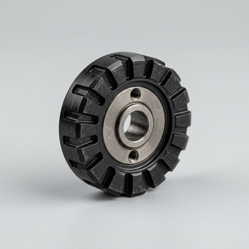
Automotive Magnetic Sensor Rotors

Precision magnet rotors for Hall, AMR, GMR, TMR, and angle-position sensing modules in automotive assemblies.

Target Buyer:Best for sensor engineers who need a rotor that is mechanically safe and magnetically repeatable under automotive validation.
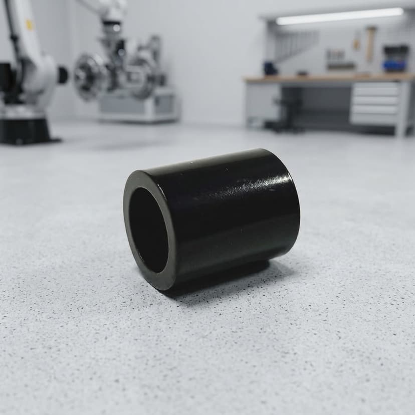
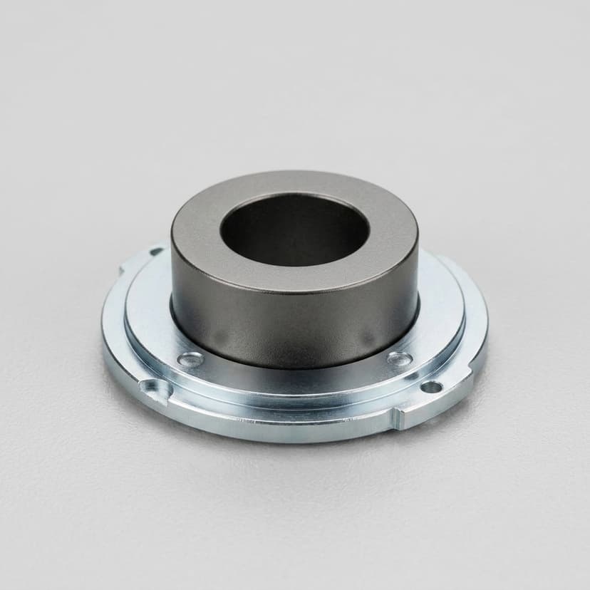
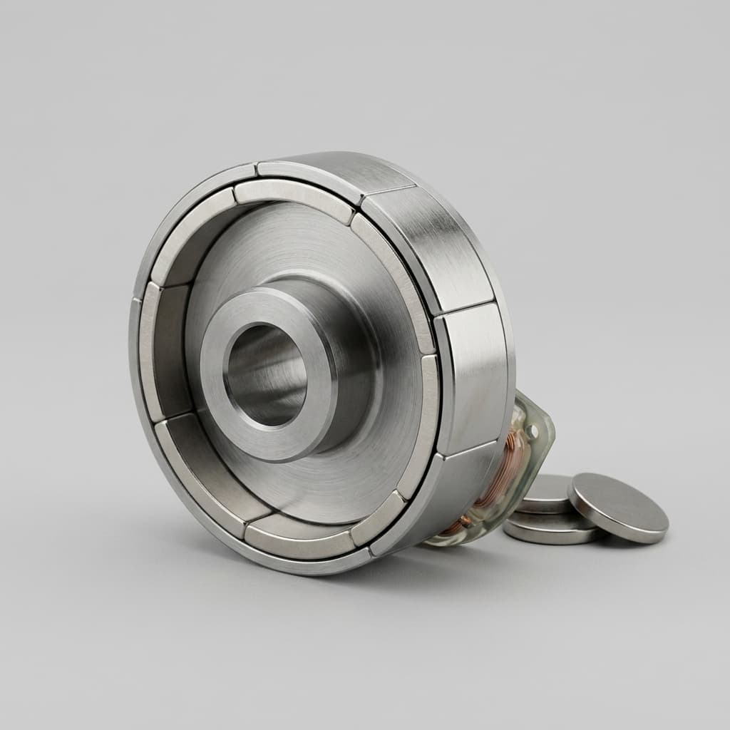
Automotive magnetic sensor rotor

Capability Highlights

  • Multi-pole, diametrical, radial, or custom magnetic patterns
  • Controlled concentricity between bore, shaft, magnet, and sensing surface
  • Suitable for pedal, steering, brake, pump, and actuator feedback modules

Typical Applications

  • Throttle pedal sensors
  • Steering angle modules
  • Brake-by-wire sensors
  • Pump actuators

Engineering Focus

  • Magnetic angle error and sensing radius control
  • Rotor balance and insert-to-magnet concentricity
  • Thermal cycling and vibration validation planning

Key Evaluation Matrix

MetricTypical RangeWhy It Matters
Magnetic angle errorProject-defined by sensor architecture and air gapAngle error is often the release gate for throttle, steering, and position-feedback applications.
Rotor concentricityDefined from bore/shaft datum to sensing surfaceMechanical runout becomes magnetic signal variation when the sensor reads a rotating magnet.

RFQ Checklist

  1. 2D/3D drawing, material target, magnetic pattern, and sensing datum
  2. Operating temperature, vibration, media exposure, and lifetime requirement
  3. Sample quantity, tooling target, annual forecast, destination, and PPAP needs
  4. Sensor IC type, target air gap, pole count, magnetic curve, and angle-error target

Risk Controls

  • Brittle sintered magnet carried into a vibration-critical assembly: Review bonded magnet material and molded geometry when chipping, cracking, or adhesive failure can affect functional safety.
  • Magnetic pattern accepted without measurable criteria: Define flux density, pole count, angle error, sensing radius, concentricity, and inspection method before sample tooling.

Buyer FAQ

Can you support custom pole patterns for sensor rotors?

Yes. The RFQ should include pole count, magnetization direction, sensor air gap, target curve, and acceptance method so tooling and magnetization can be reviewed together.

Related Resources

  • Insert molding and overmolding
  • Contact / RFQ

Inquiry Email

[email protected]

Email app

Include drawing, material, pole pattern, quantity, and destination.

Instant Chat

+8618857971991

Chat on WhatsApp

Direct response from our engineering team.